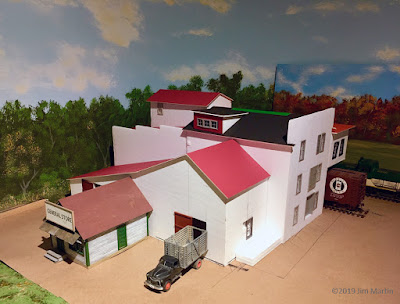
Workshop member Jim Martin checks in with a report on a new structure for his layout...
---
March was a productive month in the Martin basement. I completed the necessary corner trackwork, finished installing my battery control for the turnouts, built a roll-away paint booth, got a wee bit of scenery done, and started filling an empty back corner on the layout with my mystery mill.
| Still in-progress, but a quick coat of craft store paint brings the basic shell to life, and gives Jim an idea of what the final structure will look like on the layout. |
Some years back on The Model Railway Show podcast I co-hosted*, I had an enjoyable chat with Bob Walker. Bob’s Scratchbuilder’s Corner appears regularly in Railroad Model Craftsman.
We both agreed there’s a special satisfaction in being able to build a structure for free, or almost nothing, using accumulated materials from past projects.
So it is with Sumkynda Mill. Sumkynda Mill is currently morphing from the mock up stage into something presenting a more finished appearance.
This all began some months ago when a friend showed me the Danby Mill kit she had assembled for the HO layout she and her husband are building together. I was smitten by the look of the thing and decided I should have an S scale approximation for myself.
The Danby Mill by American Model Builders was reviewed by Trevor in the June 2003 issue of RMC. That kit was inspired by the Hinkle Mill article in the January 1982 issue of RMC. Written by Mike Small and illustrated by Julian Cavalier, it begs to be modelled. Armed with both issues, I’m attempting my own take on the rambling, rustic structure.
My total cost so far is just three dollars. That’s enough for two sheets of dollar store Foamcore for the basic structure shapes. Everything else is being sourced from various trays and boxes around the workshop.
Odd assortments of Grandt Line doors and windows are the principal second ingredients. Old, rambling mills are great for using up various sizes of windows. Also tossed into the mix are parts from damaged plastic kits, industrial fittings from Ratio, Rusty Stumps warehouse doors, a variety of stacks, scraps of wood, matboard, styrene, and so on. The bits I’m finding will inform the final design while still paying tribute to Hinkle. I think Bob Walker would approve.
Foam core is lightweight, fairly rigid and easy to work. I mortise the corners so no bare foam is exposed. Window and door openings are cut on the surface and the foam backing is gouged out. The bottom layer of paper remains. The cavity is painted flat black and once the glazed windows are installed the effect is sufficient.
 |
| Foamcore board is inexpensive, lightweight, rigid and easy to work. |
I’ve used this stuff in the past for smaller mock ups but I’m not sure it’s the final answer for something this size. Before proceeding any further, I may construct new core shapes from heavy matboard. It wouldn’t be too difficult at this stage because I can easily copy the measurements from the foam core structure with my digital caliper.
This will not be an exact copy of either Danby or Hinkle but so far I’m pleased with my efforts to capture the proportions and essential character of both mills. I would have liked a little more room on the layout to model the full width and depth of the complex but the most interesting shapes have been captured. I am adding a kit-built general store constructed and given to me by Pete Moffett. It will become the mill office.
A quickly-applied coat of craft acrylics hides the white foam. These base colours will suffice until I get around to applying various textures of building papers. I will print those onto photographic paper from my Model Builders program.
Having gotten this far, I will likely let this sit for several months before starting up again. Spring has arrived and I’m getting anxious to leave the basement and play with my outdoor toys.
One last thing: Sumkynda Mill is a name that’s going to get old pretty fast. It’s simply a play on words while I figure what kind of mill it will be. Right now I’m leaning toward wood products.
Cheers!
- Jim
(*Want to hear that episode? All of The Model Railway Show episodes are still available to enjoy. He's the link to Jim's interview with Bob Walker.)

